
One area we haven’t really talked much about is electrical. So, I thought it might be time for a post about things that have worked well and not so well for 6328. Your team may make different choices – but maybe you’ll get an idea or two!
Focus on Quality Wiring
The quality of the robot’s wiring matters. As I caution the students, just one bad connection can mean a lost match! Electrical is a great place to involve your most detail-oriented team members. Sloppy wiring not only puts your robot at risk, but it leaves a poor impression with judges, inspectors, and scouts. (When I’m walking around the pits, both the high quality and the poor quality wiring stand out immediately.) What makes good wiring?
- Right gauge and color wires
- Wires of proper length – neither stretched tight nor with large extra loops
- Neat, bundled and tied-down runs, kept as accessible as possible within the limits of the robot design.
- Tight, properly done crimps
- No exposed copper
- Serviceability – disconnection points around controllers/motors
- Carefully and securely mounted components
Main Power
Like many teams, we started out using premade 6ga wire harnesses, but quickly moved to building our own made-to-fit main power leads. Unfortunately, standard 6awg wire is hard to work with and to route in the robot. We like to use “ultra flexible welding cable” – which is high quality wire made with smaller strands and nice rubber jacketing. This is so much nicer to work with! It’s only a little more expensive, and since you typically keep these runs as short as you can a 25’ length should be good for building a bunch of robots. Here’s our current PDP showing the main power inlet and connections; note how the flexible cable bends neatly into place. The dual red lead at lower left is the run to/from the main breaker.

Wire & Power connections
We use red/black zip cord for all power circuits; it’s far easier to manage than individual leads. High-draw motors (drive, shooter flywheel, etc.) get 10awg wire to reduce voltage drop and wire heating.
For power connections, unsurprisingly, PowerPoles are our standard. We generally put them on both inputs and outputs of motor controllers, and on motor wires, so it’s easy to swap a failed component.
As good as they are, PowerPoles can go wrong in two ways:
- Bad crimps. To avoid these, start with a quality crimp tool – we use a TriCrimp – and teach students to use it properly. It’s critical to inspect and tug on every crimp before assembling the shell onto it so that bad crimps are found before they’re in the robot!
- Shell assembly. When assembling PowerPole shells, the contact must fully “click” into place, otherwise it will not contact a mating connector. As with crimps, any problems are best found now! Fun story: Our rookie year we ran a 3-motor gearbox through an entire event and a half before discovering one of the motors wasn’t actually connected because of a not-quite-clipped PowerPole contact. It made for a great lesson in pit electrical debugging, but also demonstrated how properly tuned software helps – the robot actually ran fine, it had compensated by running the other 2 motors harder!
Solenoid Connections
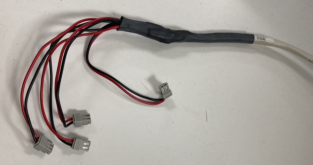
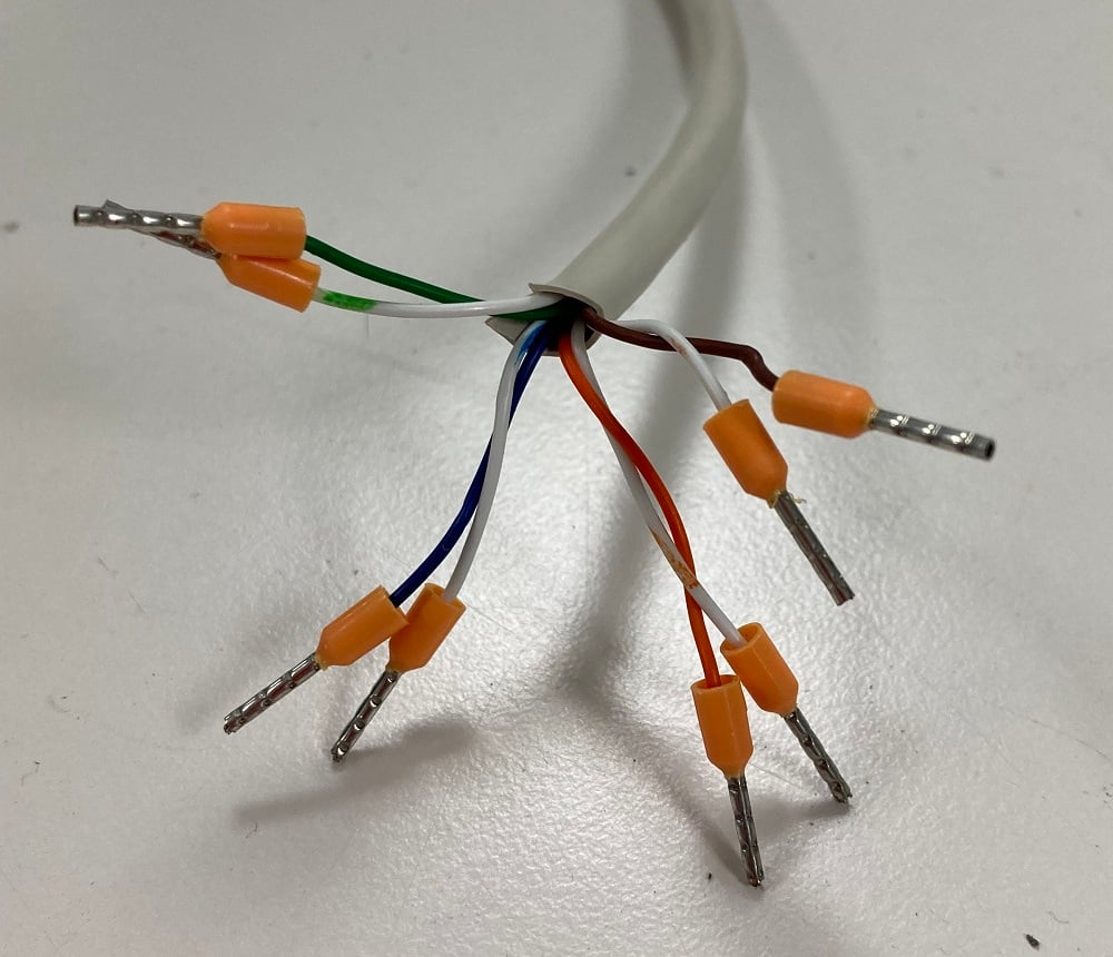
Pneumatics wiring involves running many pairs of small-gauge wire from the PCM to the solenoids. We use a piece of (stranded, copper) network cable, which contains 4 wire pairs and makes for a very neat run. Heat shrink the individual connections, then make a “boot” with a larger heat shrink to tie it all together. Be sure to label the pairs. A 6328 pneumatics harness looks like this:
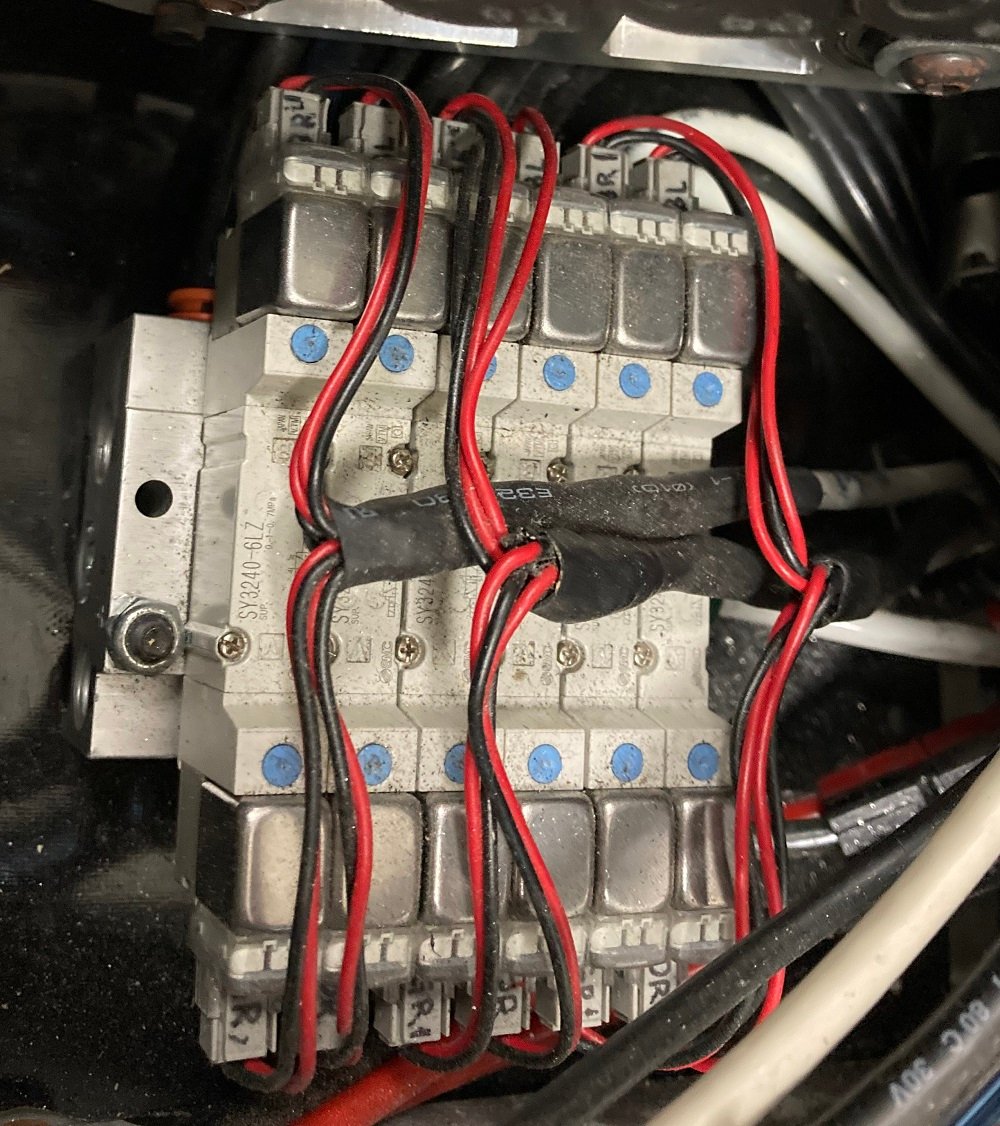
If you need more than 4 pair, just add another piece of network cable and bundle the network cables together. Done well, you’ll end up with a nice, neat assembly like this monster manifold with 6 dual-ended solenoids in our 2018 robot. If you look closely you can see that each connector has a color code written on it, matching the twisted pair it’s connected to.
775 Pro Motor connections
We’ve used 775 Pro’s a lot on our robots but wiring them was always a hassle. Their terminals are really too small for the amount of power they draw and making solid connections, especially to 10awg wire, was hard. We used to build custom flag terminal assemblies like these (from 2018):
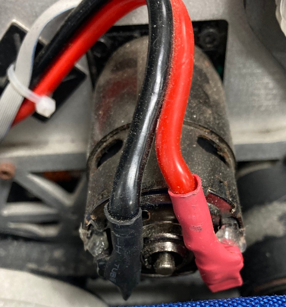
These worked, but were never great.
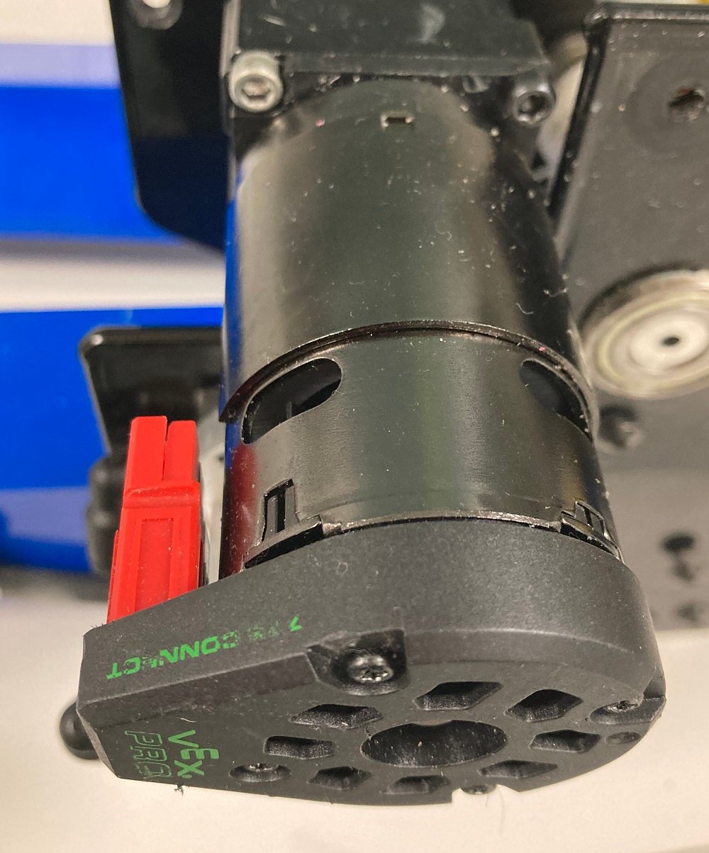
Thankfully, the 775 Connect (775 Connect – VEX Robotics) came along. After some initial skepticism, we’re converts. These are easy to solder on, protect the terminals, provide a solid connection to PowerPoles, and can even (with care) be desoldered and moved when you do burn out a motor. Now the connections look like this:
CAN Wiring
When controllers came with bare CAN wiring, we started using these JST RCY-series connectors, as we wanted a solid, solderless connection. These aren’t “latching” but have a positive detent engagement, and we had solid results with them. They’re a challenge to crimp & assemble properly, though several of our students became quite good at it.
We buy these from Digikey:
| Part | P/N | Digikey P/N |
|---|---|---|
| Housing, female | JST SYR-02TV | 455-2655-ND |
| Housing, male | JST SYP-02TV-1 | 455-2651-ND |
| Contacts for male housing | JST SYF-001T-P0.6(LF)(SN) | 455-2652-1-ND |
| Contacts for female housing | JST SYM-001T-P0.6(N) | 455-1909-1-ND |
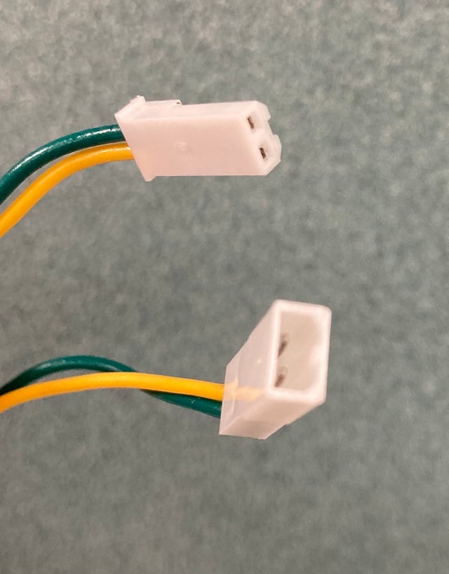
Since controllers now often come with PWM-style connectors preinstalled, we tried using them in the 2020/2021 robot:
We have not had good results with these. They absolutely require clips, since without, connections are completely insecure. Unfortunately the clips are a pain to work with and do not secure the connection much better – a hard tug will pop the clip right off. And when students put them back together, it’s all too common to reverse the connection (yellow to green) which, of course, completely breaks the bus as well. We won’t be using these going forward.
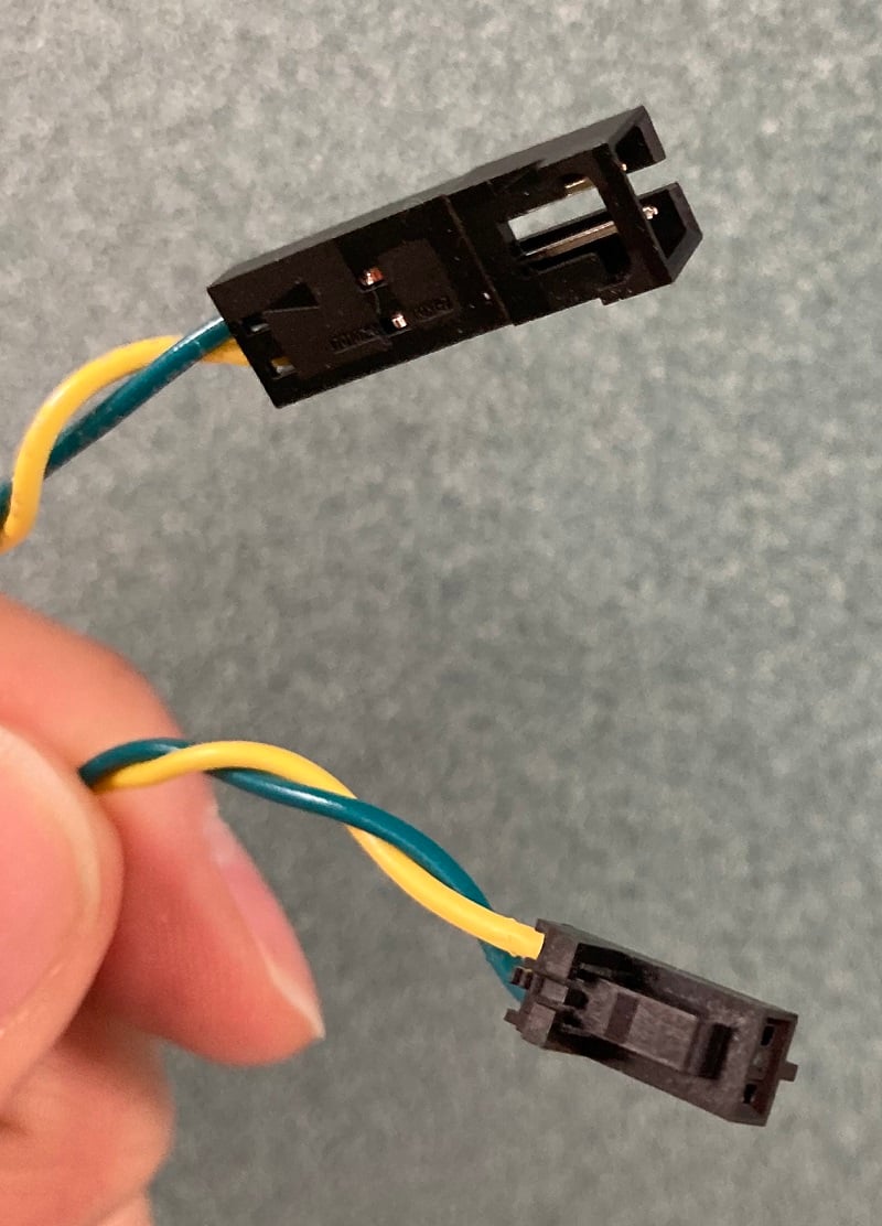
We considered going back to the JST RCY style connections, but at mentor Cameron’s recommendation, we’re now trying these 2-pin connectors with a secure locking mechanism. They are roughly the same effort to crimp as the JST ones.
For SparkMax connections, to go with the above we’re purchasing the JST-PH 4-pin connector that mates with the SparkMax, and starting to make fully custom CAN cable assemblies. This has the nice advantage that we can make the leads the length we need, instead of making extender cables (with more points of potential failure). Again, the main challenge is making the precision crimps needed; the JST-PH contacts are quite tiny. Buy plenty of extra contacts to account for do-overs.
Digikey part numbers:
| Part | P/N | Digikey P/N |
|---|---|---|
| Latching Housing, male | Molex 0050579402 | WM2900-ND |
| Latching Housing, female | Molex 0701070001 | WM2533-ND |
| Contacts for male housing | Molex 0016020086 | WM2510CT-ND |
| Contacts for female housing | Molex 0016020107 | WM2517CT-ND |
| 4-pin JST-PH connector for SparkMax | JST PHR-4 | 455-1164-ND |
| Contacts for JST-PH connector | JST SPH-002T-P0.5L | 455-2148-1-ND |
Ferrules
We generally minimize use of ferrules. They are occasionally useful on small wires but should never be used on the WAGO power connectors on the PDP (which are designed to “squish” wires for maximum surface contact). We sometimes use them on PCM solenoid connectors; here’s the other end of the pneumatics harness:
However, find that for 18ga Weidmuller connections like the compressor, they don’t engage well – the ferrules that fit the wires are too big to comfortably fit in the PCM connections.
RoboRio
The standard .1” pin connectors on the RoboRio pull out easily. Even though we generally don’t have a lot plugged into these, even keeping the RSL connected can be troublesome. After one too many times of having a disconnect, last year we bought the Swyft Robotics RoboRio JST board (JST Connector Boards – Swyft Robotics Shop 1) . So far, we’re pleased – the connections are much more secure with this, and the price was reasonable.
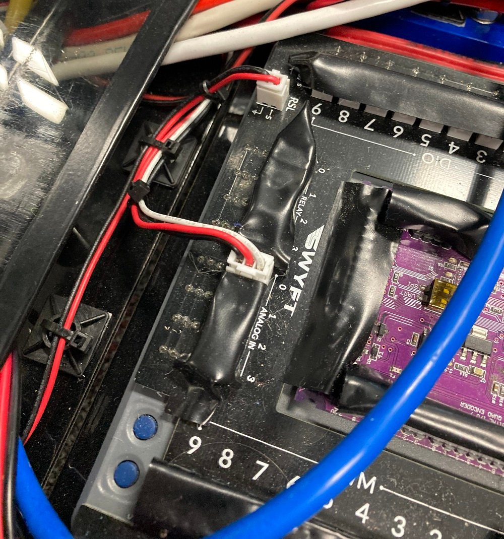
Whether using the bare Rio connectors or the Swyft board, unused connectors should be taped over, as seen above. Otherwise, the first time your mechanical team does a little drilling nearby, you may find yourself disassembling your Rio to extract the aluminum chips that are shorting out its power rails. Ask me how I know that…
Controller Mounting
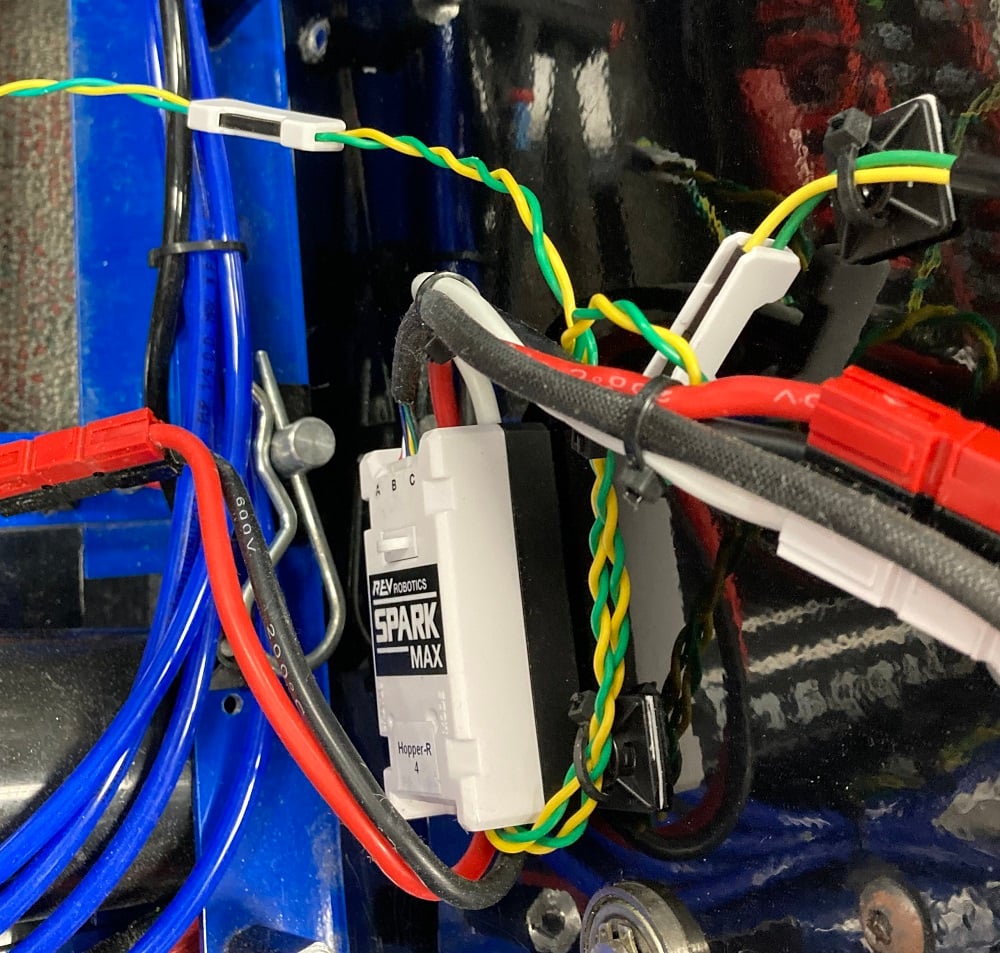
The advantages of brushless motors are compelling. One change that has brought is that we’ve moved to mounting controllers as near as possible to motors, so that we seldom have to extend the encoder connections. This also makes for more flexible placement of the PDP, since it’s not surrounded by controllers any more. For example, here are our drive controllers, mounted to a plate directly atop the gearbox:
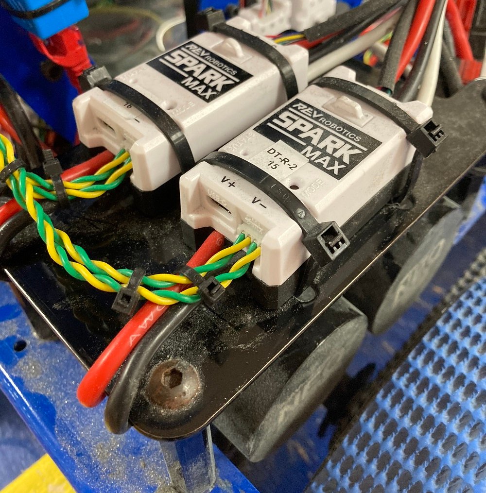
One concern with SparkMax’s is that if the CAN connector to a single controller gets unplugged, it breaks the whole CAN bus. We zip-tie the CAN wires to the power leads to prevent this, as can be seen above.
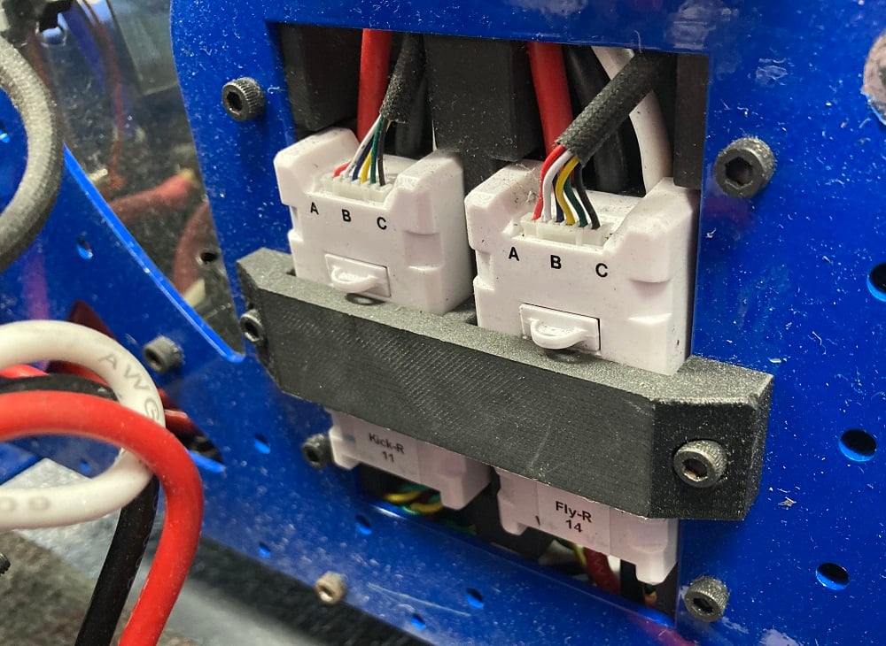
And here is a shooter and feed-roller motor controller, set into the side of our shooter assembly in a 3d-printed mount, keeping them just below the motors they control:
We hope this quick tour of 6328 wiring was useful – let us know if you have any questions or comments!