
Our robot code work this week was focused on setting up a solid foundation for our 2022 code base. Below are a few key takeaways; while none of this is particularly revolutionary, we hope that it might prove useful.
AdvantageKit, Logging, and Multi-Robot Support
This is our first full project to make use of AdvantageKit and our logging framework. This means that hardware interaction in each subsystem is separated into an “IO layer” (see more details here) such that data can be replayed in a simulator. An extra bonus of this system is that it’s easy to swap out the hardware implementation. Currently, the drive subsystem supports SparkMAXs, TalonSRXs, or the WPILib drive sim depending on the current robot. We can test our code on older robots just by changing a constant, which has proved useful as we develop code long before any competition robot takes shape. Each subsystem and command defines constants for each robot, meaning that we don’t rely on all of them to behave identically. We’ll continue to share our progress with logging as the robot project grows beyond just a single subsystem.
Operator Interface
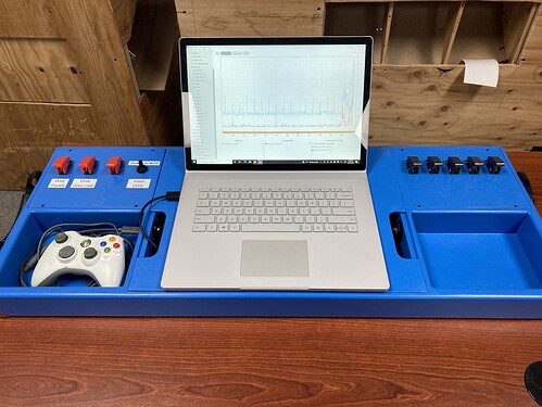
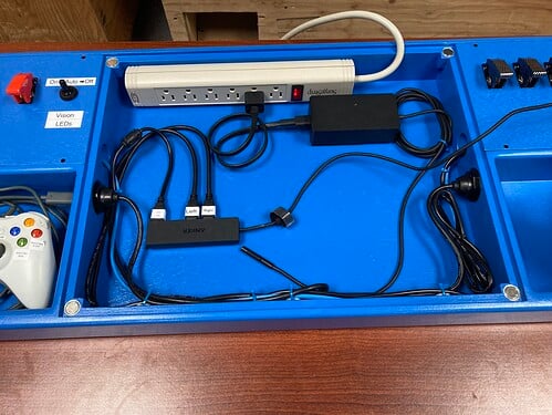
During the offseason, we built a new operator board (see below) focused on using Xbox controllers. It contains wells for the driver and operator controllers, plus a series of physical override switches. The panel under the laptop is magnetically attached, and lifts up for access to the cables. This makes it much easier to carry devices to the field, and means that we don’t need to rely on dashboard buttons for critical overrides.
Last year, our scheme for finding and using joysticks was extremely flexible (see this post). However, we felt that the capability just wasn’t worth the complexity. Rather than supporting 7+ control schemes, we’ve reduced down to just 2. During competitions, the driver and operator use separate Xbox controllers. For testing or demos, all of the controls can also be mapped to a single Xbox controller. Here’s how the code is set up internally:
- All of the driver and operator controls are defined in this interface (it’s very minimal right now). Based on the number of Xbox controllers, either the single controller or dual controller implementations are instantiated.
- This class handles the override switches on the operator board. It reads the value of each switch when the joystick is attached, but will default to every switch being off if we’re running without the board.
- The
OISelectorclass scans the connected joysticks to determine which versions of the OI classes to instantiate. When the robot is disabled, the code continuously scans for joystick changes and recreates the OI objects when necessary.
This command is responsible for converting joystick positions to drive speeds. The joystick mode is selectable on the dashboard, and we currently support 3 modes (again, simplifying from 10 modes last year).
- Tank: Left stick controls left speed, right stick controls right speed. While not a very intuitive system, this is still useful when testing the drive train.
- Split Arcade: Left stick controls forward speed, right stick controls the speed differential. This is a reliable and easy to use option for testing, demos, etc.
- Curvature: This isn’t quite a traditional curvature drive, but a mix between full curvature and split arcade. It’s a scheme we used during the at-home challenges last year to overcome the key limitation of curvature drive: not functioning while stationary. While a “quick turn” button is an effective solution, we felt that it was too unintuitive. Instead, we slowly transition between split arcade and curvature drive up to 15% speed (0% is split arcade, 15% is curvature, and 7.5% averages the outputs from both modes). This provides the benefits of curvature drive at high speed while maintaining the ease of use from split arcade.
Odometry, Motion Profiling, and Field Constants
Our current odometry system is fairly basic right now, but will evolve as we continue to explore vision options. Odometry is handled by the drive subsystem, with getters and setters for pose. One key change from last year is that everything uses meters instead of inches. This has already made our lives much easier when it comes to setting up motion profiling.
As with other areas, we took this as an opportunity to simplify older code. Our ~800 line motion profiling command from last year is now much simpler and easier to use (see here). We focused on the most essential features while removing the less useful ones (like circular paths, which were only useful for the at-home challenges). This new command is also much more maintainable when we need to make fixes and improvements.
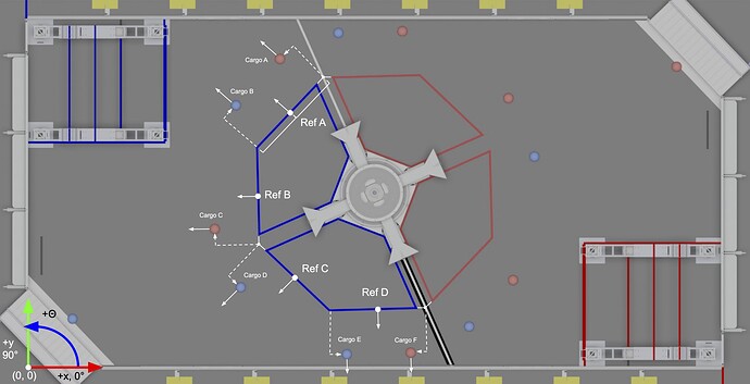
Before long, we’ll need to start putting together profiles for auto routines. Unfortunately, this year’s field layout is a bit of a mess when it comes to defining the positions of game elements (did the edges of tarmac really need to be nominally tilted by 1.5°?) To save many headaches later in the season, we wrote this class with lots of useful constants. It defines four “reference points” (see the diagram below) along the tarmac. The cargo positions are defined using translations from those references. The same principle of starting at a reference and translating could be used to define robot starting positions or waypoints on a profile to collect cargo. The class also includes constants for the hub vision target.
SysId
SysId is an incredibly useful tool, but the process of setting up a new project is quite tedious (selecting motors, encoders, conversion factors, etc.) Instead, we wrote a command that communicates with SysId but makes use of the code we’ve already set up to control each subsystem. See this example of using the command. Each subsystem just needs a method to set the voltage output (with no other processing except voltage compensation), and a method to return encoder data like position and velocity.
Utilities
Neither of these utilities are new this year, but it’s always worth mentioning them again:
- We use a custom Shuffleboard plugin called NetworkAlerts 3 for displaying persistent alerts. The robot side class can be used to alert the drivers of potential problems.
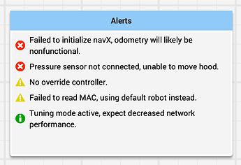
- For constants (like PID gains) that require tuning, we use our TunableNumber class. During normal operation, each acts as a constant. When the robot is in “tuning mode” (enabled via a global constant), all of the TunableNumbers are published to NT and can be changed on the fly.
Our next major software project is to explore vision options with the hub target (and maybe cargo too). We’ll be sure to post an update with our findings. In the meantime, we’re happy to answer any questions.